

Thanks to Mr. John Schmul for providing this rare document on Cinecolor. It is highly technical and relates specifically to the three-color process that the company introduced in 1950, after the advent of three color monopack films, but it does give some clues as to the methods used to print the company's two-color product. The article was based on a presentation made to the Society of Motion Picture Engineers on October 11, 1949 and published in their Journal in the January, 1950 issue.
Cinecolor Three-Color Process
By ALAN M. GUNDELFINGER
CINECOLOR CORPORATION, BURBANK, CALIF.
Summary–The basic chemical reactions, spectral characteristics of the dyes and types of machines utilized in the film processing are discussed in detail. The entire Cinecolor three-color process is described from the printing of negatives to the final inspection of the finished print.
THE CINECOLOR THREE-COLOR PROCESS is a subtractive process whose application is found primarily in the theatrical and commercial fields where many copies from an original are required.
The three-color process is designed for, and depends upon, three-strip separation negatives for its printing medium. These negatives may be obtained from alternate or skip-frame techniques such as are employed in cartoon photography and three-strip beam-splitting cameras; or separations made from monopack films, such as Kodachrome or Anscocolor. Aside from the above, it is not the purpose of this paper to delve into the technique of producing negatives but rather to describe the print process.
Because of the years of experience which the company has had in the two-color field, the controls which have been developed, and economies of operation which have been effected, the three-color process was intentionally developed along the lines of the two-color system. In other words, the attempt was made to develop the three-color method, as much as was feasible, as an extension of the two-color process.
The positive raw stock utilized is the conventional and well-known duplitized film consisting of the usual base with color-blind positive emulsions impregnated with a water soluble yellow dye coated upon both sides of the base. It is of interest to note that this film has exceptionally good projection life, outlasting prints on single coated stock.
PRINTING
Assuming that three-strip separation negatives are available, the blue record will be referred to as the yellow printer, the green record as the magenta printer, and the red record as the cyan printer. The first step in the process is to print two of the records simultaneously onto opposite sides of the positive film. While it is not essential, the common practice is to use the cyan and magenta printers in this first operation. In the same operation, the sound track is printed to the side of the film which is subsequently to contain the cyan image. As a result, the positive raw stock reaches the process department having latent images of the magenta component on one side of the film and the cyan picture component and the sound track on the opposite side. Because of the necessity of maintaining these two picture images in perfect superposition or registration, step printers rather than continuous printers are utilized.
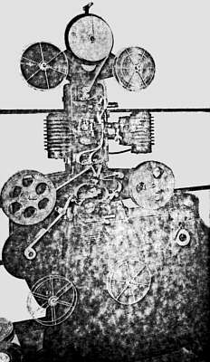
These printers, as illustrated in Fig. 1, have two lamp houses connected to the film gate by means of light tunnels. As can be seen from the illustration, the two separation negatives are brought down through the film gate with their image-containing gelatin coatings facing each other, with the positive film sandwiched in between. Before reaching the film gate one of the negatives, which has been previously edge-notched, passes through a conventional breaker box whose purpose it is to actuate a light-changing device at the instant the change of scene occurs in the printer aperture.
The Cinecolor printing machines utilize push-down pins located just above the aperture rather than the conventional pull-down pins which are usually present below the aperture. Because of this, the wear and tear on the perforations utilized for registration is minimized because, no matter how badly shrunk the negatives might be, the registration pins of the printers are caused to enter sprocket holes in the film which are no more than a small fraction of an inch away from the holes utilized for advancing the film. In this manner no punching can occur with the registration pins and, as a result, it is the rule, rather than the exception, that the steadiness and excellent image superposition of the five hundredth copy is identical with that of the first copy.
The light-change device employs a continuous loop of opaque leader which has punched in it holes of variable but predetermined size. This leader stock is advanced automatically by means of a solenoid actuated sprocket which, in turn, is controlled by an electrical contact which occurs when the notch in one of the negatives referred to above reaches the breaker box. In other words, this might be referred to as a variable area type of light changer. As shown in Fig. 1, the film, after leaving the picture aperture, continues on down to where it is met by the sound track negative and both of these films are passed over a continuously rotating conventional sound sprocket containing the typical sound aperture which is illuminated from a lamp house below.
PROCESSING MACHINES
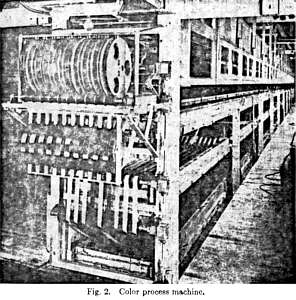
The present processing machines consist of three horizontal shallow troughs, one above the other, and wide enough to accommodate ten strands of film, as illustrated in Fig. 2. The immersion time in each solution and wash is held constant and the duration is controlled by the spacings between partitions or dams. The flow rates of the solutions and washes, as well as temperatures, are held constant. The wash water utilized in the process is brought up from several deep wells, properly filtered and passed into the main distribution tank. It is extremely fortunate that, the temperature of this well water remains quite constant throughout the year, varying between 64.5 F and 65.0 F.
Each of the ten strands of film on the processing machine, while operating at constant speed, is, nevertheless, independent of the others. In other words, each strand can be started or stopped independently at will. The linear speed of each strand is 12 ft per min, making a total output capacity for each machine of 120 ft per min.
As can be seen in Fig. 2, the rolls of printed film are loaded on a rack and the rotation of the rolls is facilitated by means of ball-bearing spindles which are slipped through the film roll hub and which, in turn, fit into a sloping slot in the rack. It should also be noted that the take-up reels for each strand are directly above the corresponding roll of film in the rack so that the entire operation of the machine can be handled from the loading end. The take-up reels are made of Bakelite and the variable speed take-up is accomplished very simply by having these reels rest upon two rapidly rotating Bakelite spools placed on adjacent and parallel-driven shafts.
The driving sprocket for each strand is just ahead of the take-up mechanism and on the same level. As a matter of fact, for each strand there are two driving sprockets on adjacent parallel-driven shafts and by means of idler rollers on a swivel bracket the film can be held down against either of the driving sprockets. One of these sprockets contains 35-mm. teeth and the other sprocket has 16-mm teeth but spaced laterally the same as on the 35-mm sprocket. This makes it possible to operate any strand with 35-mm, 16-mm, or 8-mm film interspliced in any manner. This is due to the fact that, in the substandard field, Cinecolor utilizes 35-mm width film with multiple rows of either 16-mm or 8-mm perforations so that it becomes necessary only to flip the pivoted bracket when a splice between 35-mm film and either of the two substandard films appears at the driving mechanism. While it is perfectly possible to operate the machine with this single driving mechanism, it is the practice, however, to safeguard the machine operation with several friction booster drives at the two ends of the machine in order to prevent the possibility of strands snapping due to build up of tension,
As can be seen from the photograph in Fig. 2, the film enters the machine in the top trough and progresses down the entire length to the other end of the machine where it passes over the end and down into the middle trough, where it is then going in the opposite direction. When the film reaches the driving end of the machine, it passes over the end of the trough and down into the third or bottom layer, where it is then progressing in its original direction. When it reaches the far end of the machine again, it comes out of the bottom trough past a double set of air squeegees and then progresses up into the dry box which extends the entire length of the machine. The film then moves back toward the head end where it passes through the driving mechanism and onto the take-up reel.
This very brief description of the Cinecolor process machine applies to all of the machines utilized by Cinecolor in its positive processes, with one minor exception. The three-color process involves two stages. Because of the simplicity of the first stage, which requires only a few solutions, the length of the machine permits it to be operated at twice the speed of the other machines, and thus to supply two machines utilized for the second stage of the process. To be more explicit, each machine is in itself a complete unit with respect to the two-color process, but in the three-color process three machines will do the work or create the output equivalent to two machines in the former process.
FIRST PROCESSING STAGE
When the film first enters the machine it is immersed in a conventional developer where the sound track, cyan, and magenta images are developed into silver. After a thorough wash the film is then passed by an air squeegee which blows off the excess moisture from the magenta side of the film. From here it is laid cyan down onto a solution whose purpose is to convert the sound track and cyan images into a cyan pigment. While the chemical reactions involved in this step of the toning operations are manifold and somewhat complicated, they can be illustrated in rather simple terms by the following equations:
4 Ag + 4 K3(Fe(CN)6] à Ag4[Fe(CN)6] + 3 K4[Fe(CN)6] (1)
2 Fe2 (SO4) x + 3 K4 [Fe4(CN)6] à Fe4[Fe(CN)6 + 6 K2S02 (2)
Equations (1) and (2) may be combined to show the complete reaction as follows:
4 Ag + 2 Fe2(SO4)3+ 4 K3[Fe(CN)6] à Ag4[Fe(CN)6] + Fe4 (Fe(CN)6]3 + 6 K2SO4 (3)
The above equations indicate that the reaction takes place primarily between the silver of the image, potassium ferrocyanide, and a ferric salt, and that the end products of the reaction consist of silver ferrocyanide, ferric ferrocyanide (Prussian blue) and potassium sulfate.
In addition to these reactive agents the toning solution of course contains other materials which, because of ionization equilibria and the formation of complex ions, can control the availability of the reactive ions and consequently the quantity and character of the Prussian blue deposit which is formed. It is perfectly possible to control contrast and the degree of dispersion of the ferric ferrocyanide deposit by varying quantitatively and qualitatively the composition of the toning solution. It is possible to form a coarse grainy agglomeration which produces bad grainy effects on the screen as well as the destruction of resolution and definition, or it is possible to produce a colloidally dispersed deposit which is highly transparent, free from grain, and having high resolution characteristics. It is also possible to go beyond this point and produce such a high degree of dispersion that bleeding takes place, causing once again the loss of resolution. Once all the factors are known and properly controlled, it is a simple matter to form a cyan image which has excellent grain and resolution characteristics. In addition to this, the spectral quality of this type of image is good from the standpoint of three-color reproduction, as may be seen by reference to Fig. 3. A more complete discussion of the spectral characteristics of this image will be given later.
It will also be noted from the above equations that the silver which forms the original cyan image has at this stage of the process been converted to an insoluble silver salt, namely, silver ferrocyanide, which salt is both light insensitive and spontaneously developable if brought into contact with a developing solution,
When the cyan image has been completely converted in the solution referred to above, the film then passes into a wash where the unreacted toning solution is completely removed from the film, after which the film is immersed in another solution whose purpose is to convert the silver ferrocyanide to silver bromide. At this stage the silver of the original cyan image is in the form, namely, silver bromide, where it was prior to the printing operations, with the exception that the original silver bromide crystalline structure has been destroyed. This reformed silver bromide is neither subject to spontaneous development nor is it particularly light sensitive.
It is possible, however, by controlling the character of the ferric ferrocyanide deposit surrounding these particles of reformed silver bromide to produce a degree of photographic sensitivity which is higher than that of the original silver bromide grain which existed in the raw unprinted form. By controlling further the character of the ferric ferrocyanide deposit it is possible to vary the sensitivity of the reformed silver bromide in such a manner that this sensitivity is increased in direct proportion to the decrease in exposure brought about by the masking effect of the ferric ferrocyanide image. In other words, if one were to flash expose the film containing a cyan image the amount of latent image present in every part of the picture would be constant and this constant image could be brought up into silver by subsequent development just the same as though there were no cyan image present. This is an important consideration in view of the fact that later on in the process it is desirable and necessary to produce an additional image on the cyan side of the film without interference from the cyan image already present.
Upon leaving the solution last mentioned, the film is washed again, properly hardened, and given a final wash before it enters the dry box and is subsequently removed from the machine. The carefully controlled drying operation produces no appreciable shrinkage in the film because of the protection afforded the base by the coatings on each side. When the film comes off this first machine it has on one side an unfixed photographic emulsion containing a silver image of the magenta component and on the opposite side a cyan image imbedded in a complete photographic emulsion whose characteristics are such that the effective sensitivity of the entire surface is constant irrespective of the presence of that image.
SECOND PROCESSING STAGE
The next step in the process is the printing of the yellow component through the yellow printer negative. At present, this printing operation is accomplished on machines similar to those described above. When this operational step is completed the film is ready for its final processing. It should be remembered that the yellow dye with which the emulsions of the film were originally impregnated was leached out of the film in the first developing stage so that in the second printing operation some of the light to which the film is sensitive has penetrated through to the opposite side. In order to overcome this deleterious effect, the film is floated on the developer, the first solution of the second processing stage. This brings up the yellow component in silver on the cyan side of the film and the portion of the image which has penetrated through to the opposite side is allowed to die as a latent image.
It should be noted at this point that the floating operations involved in this process present no problems due to the fact that it is possible to maintain high surface tension characteristics in the corresponding solutions. It is only on rare occasions that any trouble is encountered and this is due usually to raw stock defects. After leaving the developer, the film is washed and then proceeds into a hypo solution where the undeveloped silver bromide is dissolved and removed from both sides of the film. Following this, the film is again washed. Next in the process a bleach or oxidizing solution is used to convert the silver in the yellow and magenta component images to a dye mordant. Like the cyan toning step, this one involves a group of somewhat complicated chemical reactions which can be condensed and stated quite simply in the following equation:
2 Ag + I2 à 2 AgI (4)
As can be seen from this Equation (4), the bleaching solution contains iodine as a principal reactant, which combines with the silver of the image to form an insoluble silver iodide image that has the property of absorbing basic dyes. As in the case of the cyan toning operation, by controlling the concentrations of several of the constituents in this bleaching bath the degree of agglomeration or dispersion of the silver iodide deposit can be varied at will and controlled. It is quite evident that if the deposit is coarse the final image will have a high degree of opacity. This is due to the mordant itself and to low color saturation, not only because of the neutral component introduced by the mordant, but also because of the low saturation of the image with dye due to a high volume-to-surface ratio of the silver iodide particles.
On the other hand, the mordant image can be made so highly transparent that it is hardly visible prior to the dyeing operation, and, since the deposit consists of extremely small particles and the surface-to-volume ratio is high, the amount of dye absorption is very much greater. In this case, with the mordant having practically no opacity and with a high dye concentration in the image, the saturation of the color components is excellent. As in the cyan toning step, it is also possible to overshoot in this direction so that bleeding can occur, which of course destroys resolution.
When the bleaching step just referred to has been completed and the film has been washed, the magenta side of the film is blown off by air squeegees and the film is then floated on the yellow dye. Upon emerging from this solution, the film is washed again for a short period of time and is then passed by air squeegees to remove the excess moisture from the yellow side of the film in order that the magenta side may be floated upon the magenta dye solution. After a final wash, the film is run through the dry box and emerges as a finished three-color print.
SPECTRAL CHARACTERISTICS
The characteristics of the Cinecolor three-color process may be best demonstrated by reference to Fig. 3 which shows the spectral density characteristics of the three components balanced to equal analytical densities. It is of interest to note that the peak density of the yellow component occurs at wavelength 445 mµ, which corresponds closely to wavelength 440 mµ which is commonly weighted because of the spectral sensitivity of the human eye, and that the peak density of the magenta component corresponds to 540 mµ, which is also weighted for the game reason.
In the case of the cyan component, however, the density continues to rise beyond the weighted wavelength of 640 mµ into the infrared. This characteristic is responsible for the high fidelity reproduction obtainable with Prussian blue sound tracks when used in conjunction .with the cesium. photocell whose peak sensitivity is in the infrared.
Still concentrating on the cyan component, it will be noted that the density at 540 mµ is slightly higher than that at 440 mµ, which is the worst defect in the entire process. The degree of imbalance at these two wavelengths, however, is negligible, as evidenced by the high fidelity of color reproduction in this system. The result to be expected from this small defect is a slight reduction in the brilliance of green objects in the picture. This, however, becomes somewhat advantageous with respect to the possibility of obtaining good sound reproduction utilizing the potassium S4 photoelectric cell in sound reproducers. The over-all peak sensitivity of this type of cell, when used with incandescent exciter lamps, occurs in the green portion of the spectrum and by actual tests it has been found that the Prussian blue sound track with a slight modification of print density or sound negative gamma is just as satisfactory with this as with the cesium type cell.
It can be said, therefore, that the cyan component of the Cinecolor three-color process, while not perfect, is satisfactory. In the case of the yellow and magenta components, it can be observed in Fig. 3 that these two are excellent. The high degree of spectral quality of these three components may be illustrated in a different manner, namely, by observing the fact that the integral densities' of the three components at their corresponding weighted wavelengths are in almost perfect balance when the analytical densities of the three components are identical. In other words, as shown in Fig. 3, the analytical densities of the three components are adjusted to the value 1.45. At the same time the integral density of the yellow component at 440 mµ is 1.24, that of the magenta component at wavelength 540 mµ is 1.24, and that of the cyan component at wavelength 640 mµ is 1.23.
It may be of interest to state at this point that the conversion factors from densities, as read on the E.R.P.I. densitometers to analytical densities are 1.20, 1.30, and 1.40 for the cyan, magenta, and yellow components, respectively, when read through the Kodak Wratten 29, 61N, and 49 filters. As a result of the excellent balance between the E.R.P.I. densities of the three components and also between the integral densities at the weighted wavelengths when the three components are adjusted to equal analytical densities, it is evident that the process is capable of reproducing very accurately colors as well as neutral values. For example, if it were required to photograph a scale of reds which would be composed of yellow and magenta on the color print, the dominant wavelength of the scale should remain constant throughout. If it were necessary to maintain, for example, a low yellow integral gamma in order to compensate for a small density peak in the blue portion of the spectrum resulting from an imperfect magenta component, then a scale of reds would appear either red in the low densities and magenta in the higher densities or red in the higher densities and orange in the low densities
In addition to this, if the same condition prevailed as stated in the previous sentence, it would be impossible to reproduce accurately a scale of yellow densities since the heavier yellow densities would be lacking in saturation or conversely the lower densities would be too high.
In order to obtain a system which is capable of giving excellent picture reproduction both as to neutral and colored objects, it is essential that the spectral density characteristics of all of the components be of such a nature that a simultaneous balance will occur not only between the analytical densities or gammas but also between the integral densities or gammas. At the same time, the conversion factors between analytical and integral density or gamma should be as close to unity as possible. It has already been noted above that the integral densities are in almost perfect balance for equal analytical densities and the ratios between analytical and integral densities are 1.45:1.24, 1.45:1.24, and 1.45:1.23, for the yellow, magenta, and cyan components respectively. These ratios are approximately 1.17. Qualitatively it can be seen from the curves in Fig. 3 that there is very little density of the cyan and magenta components in the blue portion of the spectrum, very little density of the yellow and cyan components in the green portion of the spectrum, and very little density of the yellow and magenta components in the red portion of the spectrum, This makes for brilliance and high saturation of color, when desired.
The wavy neutral curve shown plotted above the spectral density curves in Fig. 3, when evaluated by means of the trichromatic coefficients indicates that the neutrals should appear to be an excellent visual gray, and this fact is supported by actual screen test. The trichromatic coefficients for a high intensity projection arc have been found to be: x = 0.3408 and y = 0.3583. Trichromatic coefficients for the arc as seen through the Cinecolor three-color neutral are: x = 0.3533 and y = 0.3423. Taking the point located by the trichromatic coefficients for the are as the white-point, the dominant wavelength of the visual gray is 538 C millimicrons, and the purity 6.25 per cent–a most adequate neutral. It can readily be seen that these values can be plotted as a point very close to the center of the Maxwell curve.