This article, provided by John Schmul, was published in the August, 1941 issue of the Journal of the Society of Motion Picture Engineers. You have to get mad at people like Hitler and Tojo for starting WWII, because stereophonic sound would very likely have become commonplace five to ten years before it finally appeared on any scale. The article is extremely technical and there are no pictures of Mickey Mouse. You have been warned.
MBH
FANTASOUND
WM. E. GARITY AND J. N. A. HAWKINS
Summary.-This paper discusses the multiple-speaker system known as "Fantasound," currently used with Walt Disney's "Fantasia."
First are discussed some of the deficiencies of conventional sound-picture reproduction, and then a very complete history of the Fantasound development. In addition, are described in considerable detail the various important elements of the system.
The art of sound-picture reproduction is about 15 years old. While an engineer familiar with the complications of sound reproduction may be amazed at the tens of thousands of trouble-free performances given daily, the public takes our efforts for granted and sees nothing remarkable about it.
Therefore, we must take large steps forward, rather than small ones, if we are to inveigle the public away from softball games, bowling alleys, nightspots, or rapidly improving radio reproduction.
The public has to hear the difference and then be thrilled by it, if our efforts toward the improvement of sound-picture quality are to be reflected at the box-office. Improvements perceptible only through direct A-B comparisons have little box-office value.
While dialog is intelligible and music is satisfactory, no one can claim that we have even approached perfect simulation of concert hall or live entertainment. It might be emphasized that perfect simulation of live entertainment is not our objective. Motion picture entertainment can evolve far beyond the inherent limitations of live entertainment.
Before discussing the operation of the Fantasound equipment, some deficiencies of conventional sound-picture reproduction may be summarized:
(a) Limited Volume Range.- The limited volume range of conventional recordings is reasonably satisfactory for the reproduction of ordinary dialog and incidental music, under average theater conditions. However, symphonic music and dramatic effects are noticeably impaired by excessive ground-noise and amplitude distortion.
(b) Point-Source of Sound.- A point-source of sound has certain advantages for mon-aural dialog reproduction with action confined to the center of the screen, but music and effects suffer from a form of acoustic phase distortion that is absent when the sound comes from a broad source.
(c) Fixed Localization of the Sound-Source at Screen Center.- The limitations of single-channel dialog have forced the development of a camera and cutting technic built around action at the center of the screen, or more strictly, the center of the conventional high-frequency horn. A three-channel system, allowing localization away from screen center, removes this single-channel limitation, and this increases the flexibility of the sound medium.
(d) Fixed Source of Sound.- In live entertainment practically all sound-sources are fixed in space. Any movements that do occur, occur slowly. It has been found that by artificially causing the source of sound to move rapidly in space the result can be highly dramatic and desirable.
It is felt that Fantasound provides a desirable alternative to the four major deficiencies just described.
There have been other attempts to provide increased volume range and a broad sound-source. It appears that three separate program channels are an essential part of any solution to these sound problems. The matter of maximum usable loudness in the theater is closely related to the number of separate program channels used.
Three channels sound louder than one channel of three times the power-handling capacity. In addition, three channels allow more loudness to be used before the sound becomes offensive, because the multiple source and multiple standing-wave pattern prevents sharp peaks of loudness of long duration.
Three tracks and program channels have other advantages over a single-channel system. Cross-modulation between different sounds can be greatly minimized. Dialog, music, and effects could conceivably be placed upon separate tracks. It should be pointed out that single-frequency steady-state measurements of amplitude distortion do not necessarily give an indication of the amount of cross-modulation that may be present in a single channel. It has been found that low-frequency transients, caused by even-order overtones, can cause objectionable cross-modulation at levels somewhat below the nominal peak overload point of the amplifier.
For economic reasons, it is almost impossible to eliminate this source of cross-modulation from single-channel reproducing systems. It is a simple matter to isolate conflicting program material on a three-channel system.
The use of three program channels allows phase differentiation to supplement amplitude differentiation in obtaining directional perspective. The phase differentiation also minimizes trouble with acoustic interference in the theater, which often accompanies attempts to use a multiplicity of horns on a single program channel.
THE DIFFERENTIAL JUNCTION NETWORK
The first step toward Fantasound occurred when we were asked to make a sound move back and forth across the screen. It was found that by fading between two speakers, located about 20 feet apart, we could simulate a moving sound-source, provided that the total level in the room remained constant. It became obvious at once that simple mechanical ganging of the volume controls feeding the two loud speaker circuits was not capable of producing the desired effect.
A special two-gang volume-control was then designed with complementary attenuations in the two circuits such that the sum of the attenuations, expressed as power ratios, equaled a constant. The formula for the relationship between the two attenuations is:
A = B - 20 log (2 sinh 0.115B)
2where A and B represent the two attenuations, expressed in decibels. Typical attenuation curves are shown in Fig. 1.
Many uses have been found for this type of network. It is extensively used in our Fantasound re-recording system to make constant output fades possible. A special 3-circuit differential junction network, nicknamed "The Panpot," is used to dub one original track onto one, any two, or all three of our Fantasound program tracks with smooth transitions and any desired level difference. Thus we simulate a moving sound-source by starting on either side-track and progressively moving the program material through the center-track to the other side-track. This move through three tracks, and thus three horns, is made smoothly by maintaining constant the total output of the three trac* and horns, regardless of the distribution among the three program circuits.
The simple 2-circuit differential junction network has been used to make smooth, constant-level fades between two sound-sources. It also has been used to vary the ratio of close to reverberant microphone pick-up without affecting the output level. It was found to be a convenient means of controlling reverberation.
FANTASOUND REPRODUCING EQUIPMENT A simplified block diagram of the reproducing equipment is shown in Fig. 2. On the left are shown the four photocells which scan three program tracks and a pilot control-track. Each program photocell feeds a variable-gain amplifier, then, through power amplifiers, the three-stage horns.
Associated with each variable-gain amplifier is a tone rectifier, which selects one of the three pilot tones on the control-track, rectifies it, and applies the resulting d-c control bias to the grids of the variable-gain stage. Thus the output from each loud speaker varies with the amplitude of its associated control tone.
TOGAD The heart, or perhaps we should call it the brain, of the Fantasound reproducing equipment is the tone-operated gain-adjusting device, abbreviated, Togad.
The Togad equipment is composed of two units-the variable-gain amplifier and the tone rectifier. A sine-wave control-tone is applied to the input of the tone rectifier, where it is transformed into a d-c bias voltage. This d-c bias voltage is then applied to the variable-gain amplifier to vary its transmission. The equipment is arranged so that a 1-db change in tone level causes a 1-db change in program transmission through the variable-gain amplifier.
Variable-Gain Amplifier.–The variable-gain amplifier, abbreviated, VGA, is a single stage of transformer-coupled push-pull pentode voltage amplification (Fig. 3). Its transmission is a function of the d-c bias applied to its grid circuit. A variation of 50 db in the transmission through the VGA can be effected by changing the bias.
A two-stage, single-ended voltage amplifier follows the variable gain stage and the three-stage unit has a maximum gain of 58 db and maximum power output of +6 db above 6 milliwatts.
The circuit features of the variable-gain stage include a balancing potentiometer in the plate circuit to balance out tone cross-talk; a loaded cathode resistor to provide high initial bias and low transmission in the absence of tone; and switches and bias potentiometers to test and adjust the bias-gain characteristic of the 6K7 variable gain stage.
Normally, the maximum level applied to the VGA input terminals is about -45/0.006w, although up to about -30/0,006w the distortion is not excessive. Hum and tone cross-talk at this point are well below tube hiss.
The change in transmission, with bias, is the result of two effects occurring simultaneously. Raising the bias lowers the mu of the tubes, thus reducing the ability of the tubes to amplify. Raising the bias also raises the internal plate resistance, which increases the ratio of mismatch between the plate circuits of the tubes and the relatively low load resistance into which the tubes look. The combination of these two effects makes the transmission a complex inverse function of the bias.
It might be noted that screen and bias regulation have a marked effect upon the bias- transmission characteristic. The external control bias, obtained from the tone rectifier, is used to "buck out" a semi-fixed bias obtained from a cathode tap on the plate supply bleeder.
The Tone Rectifier.–The tone rectifier (Fig. 4) contains four important elements:
(a) A band-pass filter in the input circuit designed to select the proper control tone and reject noise and the unwanted tones.
(b) A compressing amplifier, using a 6H6 and a 1620 tube. The output of this amplifier varies approximately as the logarithm of the logarithm of its input. The 6H6 half-wave rectifier cuts off the negative half-cycles of tone and the remaining positive half-cycles are applied to the grid of a 1620 triode functioning as a grid current compressor. Contact potential and gas current in both 6H6 and 1620 tubes are balanced out by the variable cathode-bias resistor in the 1620. This particular log-log amplifier was devised by Kurt Singer.
(c) A 1620 triode amplifier, transformer coupled.
(d) A 6H6 full-wave rectifier, whose d-c bias output is fed to the variable gain amplifier.
There are many time-constants in the VGA and tone rectifier which contribute to the total "operate" and "restore" time-constants of the combination. However, all but the time-constants associated with the 6H6 rectifier ripple filter are so small, relatively, that they may be neglected. The RC products of both charge and discharge circuits are approximately equal and the "operate" and "restore" times are about 15 milliseconds.
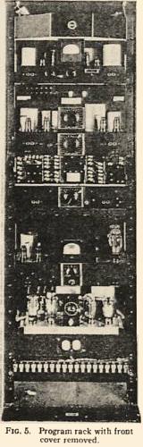
Fig. 5 shows most of the equipment used in one program channel. The topmost panel contains a pilot light. Below that is shown the tone rectifier unit. Next below is the variable-gain amplifier, which has two volume-control knobs in the center. Immediately below the VGA is an equalizer panel. Below that is a volume-control panel, and next below is a 20-watt power-amplifier. The lowest shelf contains a regulated plate supply.
In addition to the equipment shown in this rack, a program channel normally includes a single stage of preamplification ahead of the VGA and a 60-watt power-amplifier following the 20-watt amplifier. The front cover, normally used on this rack, is not shown in Fig. 5.
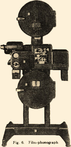
MULTIPLE-TRACK FILM-PHONOGRAPH
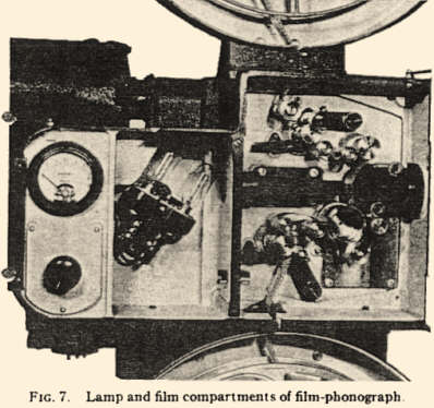
This film-phonograph, shown in Fig. 6, scans four 200-mil push-pull sound tracks simultaneously on one 35-mm. print. It is driven in synchronism with a picture projector by means of a selsyn interlock system. The lamp and film compartments are shown in Fig. 7.
Film Drive.–The sound-tracks are scanned on a curved film-gate. Constancy of film movement is obtained by the use of a magnetically driven drum which draws the film down over the gate. Flutter measurements indicate that this is a highly satisfactory driving and scanning arrangement.
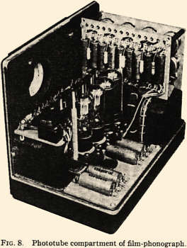
Optical System.–A single 10-volt, 5-ampere exciter lamp mounted in a double holder in the left compartment of the sound-head provides the illumination. All four sound-tracks are scanned simultaneously by a single optical system of the slitless type. The optical train consists of a light-collecting optical system which images the lamp filament as a long beam of light 1 1/4 mils high across the four soundtracks. The illuminated image of the sound-tracks is then projected by a camera and cylindrical lens system onto four multiple beamsplitter lenses which, in turn, focus each half of the push-pull soundtracks upon the respective cathodes of four push-pull phototubes (Fig. 8).
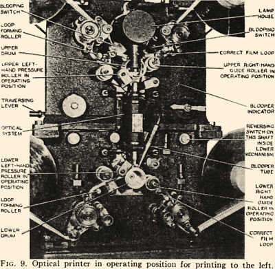
OPTICAL PRINTER
The Fantasound optical printer is designed to print four double width sound-tracks side by side across the useful area of a 35-mm film, from negatives having a standard width sound-track in the standard location. The way in which this is accomplished may most easily be explained with reference to Fig. 9, which shows the printer threaded for operation in one direction. The negative passes around under the upper drum and is illuminated by an illuminating system enclosed in the lamp-house. Below the upper drum is the optical system which projects an image of the sound negative upon the positive raw-stock running over the lower drum. Each scanning drum is driven by a magnetic drive. The optical system projects an image of the sound negative upon the positive film travelling on the lower drum. This image is enlarged in the lateral plane but not enlarged in the longitudinal plane of the film.
Traversing Mechanism.– On the left of the upper mechanism (Fig. 9) is the traversing lever which controls the position of the image on the positive raw-stock. By raising this lever and moving it forward and backward, the entire upper mechanism and optical system are moved forward or backward across the film to be printed. The traversing mechanism provides four locking positions for the upper mechanism spaced 0.200 inch apart so that the resulting sound-tracks are spaced 0.200 inch apart on the print.
Reversing Mechanism.–The printer is designed to print negatives either forward or backward; i. e., either "heads" or "tails" out, at 90 feet per minute. It incorporates simplified threading in that regardless of the direction of printing, the threading is always done in one standard manner with tight film loops. Then by operating one lever, the correct film paths and loops are formed for either direction of film travel.
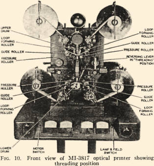
Fig. 10 shows the threading position. In this view, the arrow shaped lever is shown in a vertical position. With the reversing lever in this position, the four loop-forming rollers, guide-rollers, and pressure-rollers assume the positions shown. The negative and raw-stock are threaded as shown, over the sprockets, loop-forming rollers, and drums. It will be noted that the film loops are fairly tight when the sprocket pad-rollers are closed. Also, on each side of each drum, the film lies between the flanges of a guide-roller.
Automatic Blooping.–Automatic blooping of splices is provided on the printer. Two blooping switches are shown in Fig. 9. These switches are designed to close when a double thickness of negative at a splice passes the switch rollers. When printing to the left, the right-hand blooper switch operates; whereas, when printing to the right, the left-hand switch operates. In either direction, when the portion of the printing stock on which the image of the splice will fall, passes the end of the blooper tube (Fig. 9), the light in the blooper tube lights and blacks out the image of the splice. A time-delay mechanism synchronizes the bloop and the splice. In series with the blooper lamp is the blooper indicator lamp, also shown on Fig. 9.
Direction Indicator.–On the lower right-hand sprocket is mounted a small lamp-house for exposing an arrow-shaped image on the guiding edge of the print. An arrow-shaped detent is ground on the outer edge of the sprocket and is so arranged that an arrow will appear on the print every 32 sprocket-holes, pointing toward the start, or in the direction of travel of the print when being reproduced.
Lamp-House and Optical System.–The lamp used is the standard 10-volt, 7.5-ampere, curved-filament exposure lamp, and is housed in the light-proof lamp-house above the upper drum.
The functions of the various lenses will be explained, starting at the lamp end of the optical train. The first is a plain window which a prism keeps dust out of the illuminating system. Next is a reversing prism which rotates the image of the filament 90 degrees in a horizontal plane.
The next item in the optical train is the ultraviolet filter, followed by a plano-cylindrical lens which focuses the image of the filament in one plane only upon the negative.
Below the negative is the optical system for projecting the image of the negative upon the printing stock. The top lens system is used to project an enlarged (5 to 1) image of the negative on a plane approximately in the center of the optical system. At the center of the optical system is a condenser lens followed by an aperture. This aperture limits the illumination in both planes and is 0.471 inch long by 0.050 inch wide. The lower lens system images this enlarged image at the center of the optical system upon the printing stock and has a reduction ratio of 5 to 1 in the direction of travel of the film and a little less than 2.5 to I across the film. Thus the image of the negative on the printing stock has a ratio of I to 1 in the direction of motion of the film and a ratio of one to slightly over two across the film.
This printer has proved to be very free from flutter. The 9000 cycle loss from negative to print (corrected for 1000-cycle loss) averages less than one decibel.
HISTORY OF THE FANTASOUND DEVELOPMENT
Fantasound reproduction differs markedly in both results and equipment from standard theater reproduction. It may be of interest to follow the history of the development step by step.
A great many equipment combinations were explored on paper, probably several hundred. Of these, ten different systems have been built up and tried out, up to the time this paper was written, Even though Fantasia has been released, development has not stopped.
The Mark I system used three widely separated horns across the stage and horns in each rear corner of the house. Two tracks were used, one feeding the screen horn, or center-stage horn, while the other fed the remaining four horns selectively by means of a four-circuit differential junction network. By manipulating a manual control, the sound could be moved smoothly around the theater. Experiments with this system brought out the advantages of a broad sound-source.
The Mark II system was a simple expansion of the Mark I system, adding three horns; one on each side-wall about halfway back from the stage, and one in the ceiling at about the center of the house.
These were in addition to the screen horn and four corner horns used in the Mark I system. This system used three tracks and a 6-circuit, manually controlled differential junction network. In addition to creating the effect of moving the sound around the theater, the controls allowed side to side movements in any plane between the screen and rear wall of the house. Simultaneous fore and aft control was also available.
Up to this time it was felt that the Fantasia roadshow equipment could be manually operated by a mixer who would go along with each show. He would provide manual volume range expansion as well as control the perspective effects. However, two objections to manual operation appeared. The five controls became rather complex for one man operation and the studio felt that it would be difficult to keep all shows alike, due to the large human element involved.
The use of a pilot tone-control arrangement was suggested to avoid these difficulties, and the Mark III system came into existence to study the advantages and difficulties of a pilot tone-control track.
This Mark III system was a single-channel Togad expander, controlled by either an oscillator or a tone track. Problems of crosstalk balance, tone-program amplitude characteristic, time-constants, distortion and noise compromise, and amount of range expansion desirable, etc., were attacked.
The Mark IV system was identical with the 8-horn, 3-track Mark II system, except that Togad control replaced manual control. This system used 8 control-tones on the control track logarithmically spaced from 250 to 6300 cycles, using a preferred number series. This Mark IV system was installed in our Hyperion studios in the summer of 1939 and was used for sound and music department research until we moved to Burbank in 1940.
The equipment racks and sound-heads for this system required a floor space about 35 feet long by 4 feet wide. It used nearly 400 vacuum-tubes. All equipment appeared on jacks and almost any conceivable combination could be patched up in a few minutes.
The Mark V system, first installed at Burbank, was similar to the Mark IV system in that 8 horns, 3 program tracks, and an 8-tone control-track were used. However, by using 8 hybrid coils in the program circuits we obtained a still more flexible system. This system was in operation only one day. The equipment operated satisfactorily and no technical difficulties were encountered. The system failed only because the musical director, the music cutter, and the "enhancing mixer," could no longer remember from one rehearsal to the next, "What should come out where?"
From this extreme of complication, the pendulum swung to the Mark VI system, which used 3 stage horns, 3 program tracks, and a 3-tone control-track.
Our first serious dubbing of Fantasia was attempted on this system. Our original Fantasound dubbing set-up required 10 program mixers, each with 3 pots, designated "Left, Center, and Right" positional controls. In addition, 3 mixers with one pot each were used to handle the left, center, and right pilot tones. We soon found that the tremendous number of positional mixing cues made it nearly impossible for a mixer to handle 3 positional controls in such a way as to avoid undesirable discontinuities during moves. We then designed some differentially ganged 3-circuit pots, based on the differential junction network principle, which greatly simplified the mixing problem. This change allowed 6 mixers to satisfactorily control '24 program circuits.
The Mark VII system was the first of the RCA-manufactured systems. Functionally, this system closely resembled the Mark VI system. The only important difference lay in the use of a linear tone rectifier in place of the log-log rectifier used in our earlier systems. This changed the tone-program amplitude characteristic.
The Mark VIII system consisted of the Mark VII equipment rearranged physically. An ingenious log-log tone rectifier, designed by RCA, replaced the linear tone rectifier used in the Mark VII set-up. The second dubbing of Fantasia was done through this system. After adding a stand-by channel, this equipment was installed in the Broadway Theater in New York for Fantasia's World Premiere.
The Mark IX equipment closely resembled the Mark VIII system. The physical layout was again modified, a few minor changes were made, and two sets of rear-house horns were manually switched in to supplement or replace the left and right screen horns at several points in the picture. This system is operating in eight of the roadshows.
The Mark X system is identical with the Mark IX equipment, except that the switching and level changes in the rear horn circuits are done automatically instead of manually. The control arrangement uses a thyratron and mechanical relay system operated by means of notches on the edge of the film. This ingenious arrangement was developed by Messrs. Hisserich and Tickner of our engineering department, The Mark X system is installed at the Carthay Circle Theater in Los Angeles.
SCORING AND DUBBING
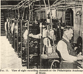
Scoring.–All the numbers, except The Sorcerer's Apprentice and the vocal portions of Ave Maria, were scored at the Philadelphia Academy of Music. Eight push-pull variable-area recording channels were used (Fig. 11).
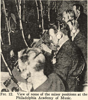
Separate channels recorded close pick-ups of violins, cellos and basses, violas, brass, woodwinds, and tympani. The seventh channel recorded a mixture of the first six channels and the eighth channel recorded a distant pick-up of the entire orchestra. The mixer handling the distant pick-up used horn monitoring, while the other mixers used headphone monitoring. Cathode-ray oscilloscopes were used as level indicators (Fig. 12). ,
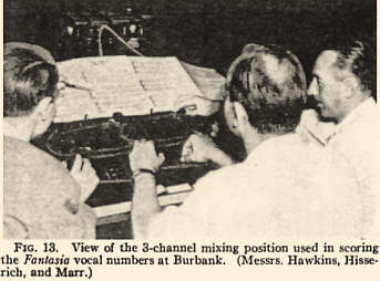
The Sorcerer's Apprentice number was done in Hollywood on a somewhat similar multi-channel system. The Ave Maria vocal numbers were recorded on three channels: two close channels, separating male and female voices, with a distant overall channel for added reverberation.
Fig, 13 shows the mixer arrangement used in recording the 3-channel vocal numbers. Three-channel horn monitoring was provided in our theater and the level-indicating oscilloscopes again proved valuable in avoiding overloads.
The necessity for checking the range compression on all channels during scoring and dubbing caused the development of a means whereby one man could visually monitor three oscilloscopes. By using color differentiation at the overload and underload points, eye fatigue was minimized. This was accomplished by masks on the face of the cathode-ray tube. An opaque mask eliminated everything below about 3 per cent modulation, including the complete negative, or downward, half-cycles. A translucent red mask covered the range from 3 to 100 per cent modulation on the positive half-cycles. Above 100 per cent modulation, the trace on the tube was not masked, and so was highly visible. Program material below 3 percent modulation (100 per cent - 30 db) produced no visible indication. Material between 3 and 100 per cent modulation appeared as a white series of half-cycles, and modulation in excess of 100 percent appeared as a brilliant green series of peaks. The recording, re-recording, and monitoring systems were poled so that the compression wave, referred to the original microphone, gave positive peaks on both oscilloscopes and galvanometers. This adaptation of the oscilloscope was devised by C. 0. Slyfield. Over half a million feet of sound negative was exposed on our scoring channels on this picture.
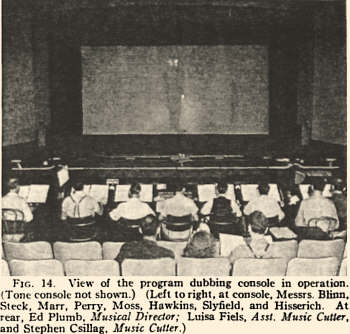
Curator's Note: Buried in the tons of historical materials written about Fantasia is an infrequent mention that Walt Disney planned to show the film in a wide screen format. Figure 14 may give us evidence that those statements were true. The aspect ratio of the projection screen illustrated here is 2.14:1. In the early 1950s, Disney released the film in a Superscope version with four channel magnetic sound. The critics panned the cropping of the film, which may have been a sloppy job, pretty atypical of anything that Mr. Disney was associated with.
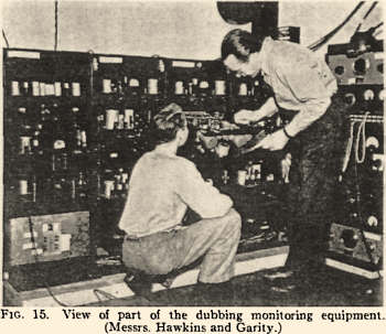
Dubbing.–Our re-recording process used 8 to 10 tracks, depending upon the sequence. Fig. 14 shows the re-recording console in operation. The output of the mixing panels fed three recorders, one for each horn channel, left, center, and right. Another channel recorded the tone track. These four re-recorded negatives were then printed on the composite quad print. The Mark VIII Fantasound reproducer was used for dubbing monitoring (Fig. 15). Including everything but release prints, about five million feet of film was used for this picture.
This history of Fantasound is far from complete. Another year and we shall know a great deal more about theater operating and maintenance problems on this type of equipment. To date, our operating and maintenance experience has been quite satisfactory.
We should like to acknowledge the suggestions and assistance of C. 0. Slyfield, W. C. Lamb, Jr., C. A. Hisserich, H. M. Tremaine, P. J. Holmes, Melville Poche, H. J. Steck, and E. A. Freitas in the development of this system. We wish to express our appreciation to Walt Disney, whose vision and willingness to encourage technical development made this system possible.