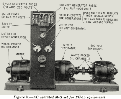
The PG-13 motor-generator set is provided with a control board which contains
a rheostat for controlling the voltage of the 12 volt generator and a rheostat for
controlling the voltage of the 600 volt generator (see Figure 36) . This panel also
contains a 12 volt meter, a 600 volt meter and a motor switch. Both rheostats are
operated through the same control knob. Push in or. the knob and rotate in either
direction until the needle of the high voltage meter comes to rest at the red line on
the dial (600 volts). Then pull out the same knob and regulate the field of the low
voltage generator until the needle of the low voltage meter comes to rest at the red
line on its dial (12 volts).
Behind the control panel and mounted as an integral part of it, is a fuse block
containing fuses for the motor and for each generator. To replace any of these
fuses, it is necessary to remove the fuse cover-plate by unscrewing the knurled
knob at the top of the control panel. The removal of this cover plate operates a
safety switch so as to automatically disconnect the high voltage fuse (plus 600) from
the generator.

The motor-generator set should run freely. See that all bearings are properly
lubricated before the set is turned on. The waste in the waste-packed oil cups should
be kept saturated with a medium grade of oil. Commutators should be clean, and
the brushes should be smooth and should fit the curvature of the commutator
throughout the width of the brush. If the brushes do not fit properly, they should
be sanded. In sanding brushes use a good grade of 00 sandpaper
(not emery). The
sandpaper should be wrapped tightly around the commutator, and should be drawn
under the brush in one direction only. Pull the sandpaper past the brush in the
same direction that the commutator usually rotates, holding the paper flush down
on the commutator. This will grind the brush down so that it has the same curvature as the commutator and will fit snugly against it. Unless the brushes are quite
smooth, and the commutators free from dirt, there will be a noticeable generator
hum in the loudspeaker.
The 12 volt generator-commutator may be reached for cleaning through a hole
in the lower portion of the end casting on the right-hand end. Use 00 sandpaper.
Do not clean the commutator while the machine is running. Turn it by hand. Follow
the same procedure to clean the commutator of the 600 volt generator.
Copyright 1930 RCA Photophone, Inc.
27
