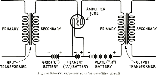
130. Voltage and Power Amplification. -In normal operation, practically no current flows in the grid
circuit of a vacuum tube amplifier, therefore, the chief
requirement to be met by all amplifier stages except that which supplies the speakers is that
the voltage of the electrical pulsations must be "stepped up" sufficiently to operate the power
amplifier tubes efficiently. The power amplifier tubes and their associated output circuits must
be "heavy duty" in the sense that they must be capable of delivering sufficient power to
operate the loud speakers connected to them at or near their maximum ability.
131. Parallel Operation of Vacuum Tubes.-Except in special cases, parallel operation of
vacuum tubes is used only in stages of power amplification. It is used when one tube is not
capable of supplying the necessary power for the operation of the loud speakers. Two tubes
in parallel will deliver twice the power of one tube,
and three tubes in parallel will deliver three times the power of one tube, etc. The grids of all
tubes used in parallel are connected together, as are the plates.

132. Push-Pull Amplification.-Push-pull amplification requires two tubes of the same type in
each stage. The grids of the tubes are not connected together, as is the case in parallel
operation, but are connected to opposite ends of a mid-tapped transformer secondary. See
Figure 90. The mid-tap is used as a common connection for making connection to the negative
"bias" potential of the grids. As was stated before, the grid voltage varies due to the impressed
alternating voltage, which causes the grid to be alternately more and less negative. In pushpull operation the grid of one tube is most negative when the grid of the other tube is least
negative; therefore, as the plate current of one tube increases the plate current of the other
tube decreases. To describe this action the word "push-pull" was coined. The action is similar
to the operation of a hand-car, where one operator pushes on the cross bar as the other pulls,
and vice-versa. A push-pull parallel stage is one in which two or more of push-pull circuits are
used in parallel as shown in Figure 91.
7
