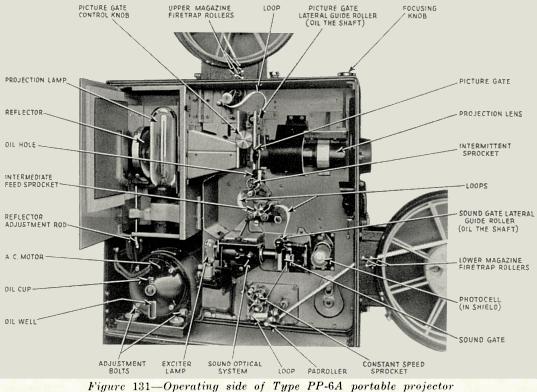
The lower part of the projector contains the sound reproducing mechanism. This may be one of two
types, each of which correspond in most respects to those used on RCA Photophone theatre
equipments. The Type PP-6A uses the mechanism shown in Figure 132, the drive side of which is
illustrated in Figure 133. This is similar to the mechanism used on Types PG-1 to PG-10 Photophone
equipments, and has been completely described in Chapter VIII. The constant speed sprocket on this
projector is controlled by the viscous damping device described there and in section 71. The damping
device is lubricated and adjusted in the same way as that in the other sound heads, except that the
adjustment screw and grease cup are located as shown in Figures 132 and 133. The sound gate used is
similar to that illustrated in Figure 62 and described in section 91.

The other type of projector (PP-6B) uses an impedance roller and fly-wheel in conjunction with the
constant speed sprocket to maintain constant film speed, and the sound gate illustrated in Figure 66
and described in section 99. Due to the rapidity with which the projector motor comes up to speed,
there would be danger of the film breaking in bringing the impedance flywheel up to speed, if no
provision were made to lessen the strain. This is taken care of by driving the constant speed sprocket
through a coil spring. The coiling of the spring while running takes approximately four sprocket holes from the lower loop and must be provided for when
threading. A loop of from eight to ten sprocket holes is satisfactory. Figure 134
shows a close-up view of the operating side of this mechanism with film threaded.
Figure 135 illustrates the drive side, showing differences of construction and lubrication as compared to the drive side of the other model, shown in Figure 133.
3
