This paper was presented to the S.M.P.T.E. convention at Los Angeles, May 1, 1953, by Mr. John K. Hilliard, Altec Lansing Corp. It was published in The Journal of the SMPTE in Vol. 61, September, 1953. This paper presents a unique view of stereophonic sound technology during the brief window of time between the openings of Cinerama and CinemaScope. Have Mr. Peabody fire up the Wayback Machine and take a look at a theatre technology in its earliest form. There are 10 illustrations included.
Thanks to John Schmul for his efforts in providing the article and illustrations.
Illustrations courtesy of Dan SherlockMBH
By JOHN K. HILLIARD
Microphones, loudspeakers and amplifiers now being installed for stereophonic reproduction of motion pictures in theaters are described. Detailed characteristics of the individual components are analyzed along with methods of providing proper equalization. Typical installation methods are also outlined.
Many persons attending the spring 1953 Convention of the Society heard demonstrations of practical theater stereophonic sound for the first time. The Program Committee wisely included visits to Cinerama, demonstrations of CinemaScope, and other methods in the formal program of the Convention; and three-dimensional color with WarnerPhonic sound is currently being shown to the public.
The Paramount, New York, was probably the first theater which for normal operation used a stereophonic system. This theater is using 75 w of audio power on each of the three stage loudspeakers, and 150 w from the regular theater sound system is available for the auditorium loudspeakers. It has been found necessary for the three amplifier systems and three loudspeaker systems which operate from the stage area to be absolutely identical. The Paramount, New York, has 256-type power amplifiers and loudspeaker systems.
The Roxy Theatre, Loew's State, Loew's Capital and other Broadway, New York theaters are now being equipped with 75-w amplifiers and A-2 loudspeaker systems.
The Paramount Hollywood is an identical installation with the exception of the use of a Westrex magnetic reproducer in the Paramount Hollywood, and an RCA magnetic reproducer in the Paramount Downtown, Los Angeles. In the West Coast Theatre, Long Beach, A-4 loudspeaker systems are used in connection with Simplex 60-w amplifier systems and a Stancil-Hoffman reproducer. For the CinemaScope demonstration on the Fox Western Avenue lot, Altec A-l loudspeaker systems driven by 75-w amplifier channels provide the sound source. In the various review rooms where demonstration films are now in progress, it had been customary to use A-4 loudspeaker systems for the smaller rooms and the A-2 loudspeaker systems for the larger rooms. The equipment details of the installations which have been mentioned are typical of approximately 30 installations in various parts of the country for public showings of Warner's House of Wax and other stereophonic pictures which are shortly to be released, as well as for limited demonstrations of CinemaScope.
In planning installations, it has been found absolutely necessary that the three stage loudspeakers be identical in size and type. When these loudspeakers are merely similar rather than identical, the true stereophonic effect is not obtained and dialogue or sound effects tend to jump from location to location in disconcerting discontinuity. It is also believed that it is necessary for the three stereophonic amplifier systems to be identical, since very curious effects have been observed where efforts have been made to use amplifiers which may appear to be similar but which are not identical.
It may be that future experience will determine that some latitude exists in this matter, but our knowledge to date causes us to stress the belief that the use of identical equipment and very careful matching adjustments between the three channels of the stereophonic systems are essential.
Description of Apparatus
Fig 1. Click Here To See Large Drawing
Figure 1 is a block schematic of the essential elements for the reproduction of three-channel, stereophonic sound. Included in this block schematic is the regularly used two-machine booth equipment.
Plans for the showing of such pictures as Warner's House of Wax, use the three channel magnetic stereophonic system for the loudspeakers back of the screen. The right-hand, or No. 2, projector photographic track carries the sound effects through the existing amplifier system to the auditorium speakers located on both sides and the rear of the auditorium. The left-hand, or No. 1, projector photographic track carries the normal release sound track; and can be used as the primary source of sound through the center speaker if the magnetic system fails.
Currently installed three-channel magnetic machines have low impedance heads. Certain to the studio-type reproducers, such as the RCA, Westrex and Stancil-Hoffman machines, have the associated three preamplifiers as an integral part. Experience today is not sufficient for a definite recommendation as to the best position for the preamplifiers. In some cases it may be convenient to put them on the front wall or on the main rack with the balance of the stereophonic amplifiers. The Altec A-150-A used for this purpose has the three magnetic head preamplifiers, a self contained power supply and three-step type of gain controls which are ganged together and operated by a single knob.
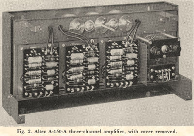
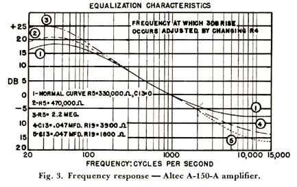
Figure 2 is a front view of the amplifier with the cover removed. The frequency response of the amplifier determines the entire response of the system and is shown in Fig. 3. The input transformer on each of these preamplifiers has connections so that several impedances, such as 30, 150, 300 and 600 ohm are available.
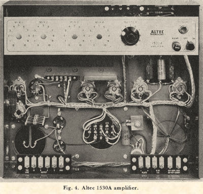
The gain controls are 100,000-ohm, 20-step, 2-dB/step potentiometers inserted between the third stage and the cathode follower. The output of each preamplifier is connected to its respective power amplifier. The Altec 1500-series amplifiers are provided for this purpose. The 1530A amplifier is shown in Fig. 4. It has a gain of 75 dB with a frequency response of +/-1 dB over the range of 20 cycles/sec to 20 kc. The power output is a nominal 70 w and the power curve is shown in Fig. 5. The output noise level is -43 dbm. Load impedances of 4, 8 and 16 ohm and a 70-v line (70 ohm) is provided. It occupies 1' m. of rack space.
The 1520 amplifier is an alternate lower-powered unit with essentially the same specifications as the 1530 amplifier except that its power output is 35 w.
The AQ-2796 switching panel is designed to distribute the output of the three channel, magnetic amplifiers to the back stage loudspeakers, the photographic tracks to the proper auditorium or emergency system and provide a selectable monitor. In addition to these functions it provides the facilities to switch to single-channel or flat operation.
The output of the three-channel magnetic track is fed through the output panel to the right-hand, center and left-hand loudspeaker systems back of the screen.
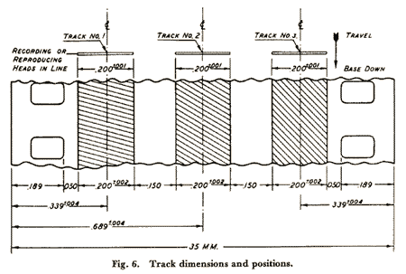
Present Motion Picture Research Council standards specify the relative track vs. speaker locations as follows: The No. 1 track is designated as that which feeds the audience left speaker The No. 2 track feeds the center speaker and the No. 3 track, the audience right speaker. On the reproducer, the No. 1 reproducer head is away from the operator (Fig. 6).
Motor Systems
Due to the shortage of motor systems, several types of interlock and synchronous motors are used. The motor system which appears to have the best possibility of standardization is the two pole, single-phase motor. This motor is coupled to the standard projection machine induction motor by a timing belt or chain, with a pulley ratio of 49: 40. The two-pole motor is thus driven at an approximate speed of 1440 rpm. This "piggyback" method allows the projector to be interlocked with the other projectors and the three channel magnetic machine, by tying all of the rotors together. The projector can be started and operated separately with the induction motor or it can be thrown to interlock position, so as to be driven in step with the other machines.

The use of single-phase excitation for the interlock is practical because of the large difference in its normal speed of 3600 rpm and its driven speed of 1440 rpm. Conventional interlock equipment in the past has used four-pole motors and it was necessary to use three-phase to prevent runaway. This difference between normal and driven speed is the ratio of 1800 rpm to 1440 rpm. Also the two-pole motor enables the operator to frame up the motor and shutter on a no-error basis.
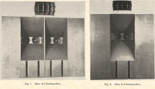
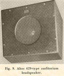
Figure 7 shows the Altec A-2 loudspeaker system which is normally supplied for theaters having more than 1600 seats. For theaters having less than 1600 seats and studio review rooms, the A-4 system is used (Fig 8). Figure 9 shows a typical auditorium speaker. As many as 26 of these 629-type loud speakers are used in the larger theaters and in the smaller theaters approximately 15 units are provided.
Cinerama Installations
Present Cinerama sound systems use five A-2 loudspeaker systems back of the screen and eight two-way loudspeakers in the auditorium. A seven-channel magnetic track is employed with five channels for the auditorium speakers.
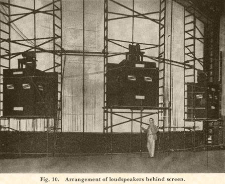
The loudspeakers back of the screen are symmetrically placed with the outside speakers being near the edge the screen (see Fig. 10). Two multi cellular, high-frequency horns are used with each loudspeaker system. The necks of the high-frequency horns are crossed so that the peripheral contour of the two horns is continuous and will give 180° distribution, and can thus cover the entire audience area. Each one of these speaker systems is powered with an Altec 75-w amplifier. The signal-to-noise ratio in this overall system is approximately 58 dB, the limiting factor being the residual background noise of the tape. The amplifier signal-to-noise is maintained at 63 dB. The use of auditorium speakers in general requires that the signal-to-noise ratio be improved over that necessary for stage speakers only. The auditorium speakers are located relatively close to some portions of the audience and a high signal-to-noise ratio must be maintained, so that this noise will not mask the sound coming from the backstage speakers or be audible during the long intervals in which no signal is coming from the auditorium speakers.
Originally it was considered necessary to mute the auditorium speakers during intervals of no signal, but it was found that when adequate signal-to-noise ratio was maintained, this function was not necessary.
70-v Distribution System
It was mentioned earlier that a 70-v tap was supplied on the output of the power amplifiers. This 70.v system is comparatively new in theater sound engineering. Negative feedback on power amplifiers provides a low internal output impedance and its use approximates a constant-voltage output source.
When we refer to a 70-v or constant-voltage distribution line, it is not meant that the voltage on this line is always 70 v., any more than we mean that the power drawn from a 70-w power amplifier is always 70 w. The 70 v is the maximum voltage on peaks at the output of the amplifier. Acceptance of this standardized voltage means that the rated load impedance of amplifiers of different power capacity has been chosen so that the voltage peak is the same for a low-powered amplifier as for a high-powered amplifier. For example, to produce 70 v at rated power on a 70-w amplifier requires that the load impedance be 70 ohm. In the case of a 35-w amplifier, the load impedance should be 140 ohm. In a loudspeaker distribution circuit such as used for the auditorium speakers, each loudspeaker will have an associated transformer which permits the impedance at this point to be adjusted to a value proper for use with the 70-v system. Thus, if an individual loudspeaker requires 5 w, the 5-w transformer tap is used, which makes its impedance such that it will draw 5 w of power when connected to the 70-v output of either a 70-w amplifier or 35-w amplifier. The same loudspeaker can be arranged to take lower or higher power by the use of a different tap on the transformer.
In practice the connection of a number of loudspeakers becomes very simple. First, the power needed for each loudspeaker location is determined and the transformer tap is chosen which will give this power on the 70-v circuit. The power required for all the loudspeakers is added up and an amplifier chosen which is capable of supplying at least this amount of power. All loudspeaker transformer inputs may then be connected in parallel to the 70-v output of the amplifier without any further consideration of impedance relations.
The use of the 70-v or constant-voltage distribution system provides a high degree of flexibility in adjusting the power to each speaker. Within its capabilities, the constant-voltage distribution system is very similar to the concept of a 110-v system as employed in our conventional 60-cycle distribution for domestic power. The voltage remains constant until the output of the generator is exceeded, and at that point, the system is overloaded. Another advantage is that the current in the distribution line is lower than with the conventional impedances used on loudspeakers such as 16 ohm or lower. This permits the use of smaller-sized conductors and allows them to be placed along the walls of the auditorium in an exposed manner if necessary. There are many suggested magnetic and photographic sound-track combinations that may be used with the various types of picture presentation.
At this time, however, it appears that any and all of these pictures require a minimum of three-channel stereo sound. The equipment recommended thus becomes a basic part of all systems
Discussion
Arthur C. Blaney (RCA Victor Div., Hollywood, Calif.): In dealing with a number of these installations have you encountered a lot of hum problems - the usual thing you would expect in magnetic reproducing systems?
Mr. Hilliard: I certainly think that every one has had trouble with them, but they have been able to work on them within established limits. We will always go through a period at the beginning similar to the rush that we are in now. Many small troubles will annoy us at the time of installation; but after a few of these installations are over, the problems will be greatly reduced, since there are no basic difficulties in design.
V. Kramer (Universal International Pictures): Did you say that No. 1 Channel is always away from the operator?
Mr. Hilliard: That’s the way it has been designated.
Mr. Kramer: On some of these reproducers where the magnetic heads are on the outside of the drum, wouldn't that put the track towards the operator? Are the emulsions wound out or wound in on the reel?
Mr. Hilliard: I don't know about that. The reason I mentioned it was so that those people who are not aware of the Research Council recommendation could investigate it and if they wish, could conform with that practice.
Dr. J.G. Frayne (Westrex Corp.): Two different practices are followed with respect emulsion position. In converted theater-type dummies the coating is on the outside of the reel and the No. 1 track is then furthest from the operator. In the case of cabinet-type three-track reproducers the emulsion is generally wound inside. In this case the No. 1 track is nearest the operator.
John Volkmann (RCA Victor Div., Camden N.J.): With regard to the surround speaker in the case of the WarnerPhonic system what spacing are you using between the centers of the loudspeakers?
Mr. Hilliard: That must, of necessity vary with the geometry of the house, and I'm quite sure that the practice is to try to space them as uniformly as possible insofar as the seating arrangement is concerned. As I indicated, the smaller houses have 15 and I believe the Roxy now has as many as 33 or 35 to get uniformity of loudness without having the sound exaggerated in any one particular position.
Mr. Volkmann: It might be of interest to the group here to know what rule has been followed in RCA stereophonic installations; namely determine the average height of balcony ledge above the floor, multiply it by two, and that should be approximately the spacing between the direct-radiator surround speakers. This rule is for loud speakers which have a distribution factor not less than 60°. In general, direct radiator loudspeakers have varying distribution characteristics in the range of 60 to 90°. In the balcony the same spacing used and the axes of the loudspeakers in general are directed so as to cover approximately half the distance across the room.
Dr. Frayne: In Mr. Hilliard’s very excellent presentation he spoke of true stereophonic sound. I wonder if he would like to define what is meant by true stereophonic sound.
Mr. Hilliard: I do not have any simple answer to that question. I think we will all have to struggle through this thing until we finally find an ultimate position which gives good stereophonic reproduction.
 Fig 1. Click Here To See Large Drawing