We can thank both Walter Shilling and Robert Perrine for providing copies of the Fairchild Installation and Operation Manual. I believe this manual, along with the Altec Service Manual, will provide a better understanding of this directional sound system that saw a flurry of use from 1954 thru 1957.
MBH
Date - 12 March 1954
Reissued 17 March 1954
Reissued 27 April 1954
THE PERSPECTA STEREOPHONIC SOUND INTEGRATOR
Manufactured by
FAIRCHILD RECORDING EQUIPMENT COMPANY
Whitestone, New York
under license from
Perspect-A-Sound, Inc.
Patents Pending
INSTALLATION & OPERATION MANUAL
FAIRCHILD MODEL 315
PERSPECTA STEREOPHONIC SOUND INTEGRATOR
INDEX
DESCRIPTION
SECTION
NUMBER OF
PAGES
DATE OF
ISSUE
GENERAL
I
2
4-54
DESCRIPTION
II
1
4-54
SPECIFICATIONS
III
2
4-54
INSTALLATION
IV
2
4-54
CALIBRATION REEL
V
1
4-54
ADJUSTMENTS
VI
3
4-54
OPERATION
VII
1
4-54
SERVICE
VIII
1
4-54
SECTION I
GENERAL
The FAIRCHILD Perspecta Stereophonic Sound Integrator is the key electronic unit in the Perspecta Stereophonic Sound System, designed and developed by Perspect-A-Sound, Inc.
This unit takes sound and speech from a single optical track and distributes it to a three-channel stereophonic system in accordance with control information recorded on the sound track in the form of three sub-audible carriers.
This means that the viewing audience will hear sounds from three sources behind the screen in any combination of direction and intensity required by the action and content of the picture material then showing on the screen.
When a non-Perspecta Sound picture is being projected an AUTO-SWITCHING control deactivates the Perspecta Sound feature and channels the sound through the center speaker system, making the side channels inoperative.
The FAIRCHILD Integrator is made in three models which differ only in the amount of gain built into the front end of the unit:
(1) the FAIRCHILD Model 315B-1 Integrator has zero gain and consists of the following units:
(a) Integrator Unit per R21477
(b) Power Supply Unit per G21518(2) the FAIRCHILD Model 315B-34 Integrator is identical with (1) above except that a FAIRCHILD Model 652 Preamplifier is incorporated which contributes a gain of 40 db.
(3) the FAIRCHILD Model 315B-60 Integrator is identical with (2) above except that it incorporates ahead of the preamplifier a FAIRCHILD Model 823 Input Transformer boosting the gain to 60 db.
SECTION II
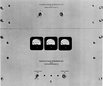
DESCRIPTION The physical size and shape of the FAIRCHILD 315B-1, 315B-34 and 315B-60 Integrators are identical.
A. The FAIRCHILD Integrator Unit:
Size: 19" Wide by 102" high by 13" Deep
Weight: Net - 39.2 pounds
Mounting details: For mounting in a standard 19" rack or 19" equipment cabinet.
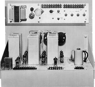
B. The FAIRCHILD Power Supply:
Size: 19" wide by 5-1/4" high by 10" deep
Weight: Net - 10 pounds
Mounting details: For mounting in a standard 19" rack or 19" equipment cabinet.
SECTION III
SPECIFICATIONS
1. INPUT IMPEDANCE AND LEVEL:
Model 315A
600 ohms
0 dbm
Model 315A- 34
100,000 ohms (can be
used to bridge 600 ohm circuit)
-40 dbm adjustable
Model 315A-60
600 ohms, 250 ohms or 50 ohms
-60 dbm adjustable
2. OUTPUT IMPEDANCE AND MAXIMUM LEVEL:
Designed to work into 600 ohms load.
Calibration signal of 70%. Track modulation 100% per Test Reel No. P1. Produces an output of -4 dbm +/-2 db all channels.
Maximum output = +2 dbm.
3. CARRIER FREQUENCY:
Left channel - 30 cycles
Center channel - 35 cycles
Right channel - 40 cycles4. CARRIER LEVEL:
Maximum carrier amplitude 16 db below a 100% modulated sound track produces a reading of "70" on the carrier meter. Individual carriers have adjustment which can compensate for as much as 12 db loss in low frequency response of the projection equipment.5. FREQUENCY CHARACTERISTIC OF CARRIER FILTERS:
(a) Flat top within 0.5 db for a 2 cycle band width.
(b) 3 db point 2 cycles from center frequency.
(c) 20 db point 5 cycles from center frequency.
6. CARRIER CONTROL CHARACTERISTICS:
(a) Range of carrier control at least 20 db.
(b) Operate and release time 600 milliseconds.
7. FREQUENCY CHARACTERISTIC SPEECH CHANNELS:
+/-1 db, 70 to 10,000 cycles 8. HIGH PASS FILTER CHARACTERISTIC:
(a) Minimum attenuation in the carrier frequency band: 25 db.
(b) 3 db point on the characteristic curve is at 63 cycles.9. LOW PASS FILTER:
(a) 3 db point on the characteristic curve is 63 cycles (b) Slope 18 db/octave 10. DISTORTION: Less than 3% harmonic at the output of each control amplifier at 0 dbm.
11. POWER SUPPLY:
(a) AC POWER: input 75 Watts at 117 Volts, 50 or 60 cycles AC
(b) DC POWER: output 275 Volts, +10 at maximum of 95 milliamperes.
(c) NEGATIVE BIAS: (1) -20 volts, (2) - 18- volts, (3) Variable from - 5 to - 10 Volts, (4) � 5 Volts.
(d) PHOTO CELL SUPPLY:
Four adjustable from 60 Volts to 90 Volts. Maximum drain 1 ma per position.12. AUTO-SWITCHING:
- Adjustable so that a steady carrier reading of "50" on any one or more meters operates the unit in Perspecta Stereophonic Sound condition. When all carriers read less than "20" the auto-switching returns the system to non-Perspecta sound operation (single channel operation).
- Time constant "operate" 6 to 12 seconds. "Release" 1 to 2 seconds.
- Cuts left and right channels by more than 26 db in non-Perspecta Stereophonic Sound condition. Center channel gain adjustable.
13. PROJECTOR SPEED TOLERANCE:
The design specifications of the FAIRCHILD Integrator unit permits proper operation with
projector speed variations of +/-4%.
SECTION IV
INSTALLATION
1. The Integrator should be installed in its rack or cabinet at some convenient place as remote as possible from heavy AC fields.
2. The Power Supply should be installed in any convenient location in the same rack or cabinet, or nearby rack or cabinet, preferably not closer than 52" from the Integrator Unit.
3. INPUT WIRING:
Special Note
a. Model 1:
For 0 dbm inputWhen facing the back of the Integrator Unit, the left and center input terminals are the input
pair. The center terminal is the ground side of the line and the right terminal is a shield ground connected to the FAIRCHILD Integrator chassis .
b. Model 34:
For -40 to -20 dbm inputConnections to the input terminals same as (a) above.
c. Model 60:
For -60 to -40 dbm inputThe left and center terminals connect directly to the 600 ohm winding of the input transformer and neither side is grounded. The right terminal carries the shield ground as indicated in (a) above.
GENERAL NOTE
When installing the FAIRCHILD Integrator care must be exercised to see that low frequency response of the photocell circuit and preamplifier is good enough to come within the range of adjustment provided as listed in SECTION III, Paragraph 4.
If there is a high pass filter in the line or amplifier, it must be removed.
4. (a) Connect the output of the common optical speechline from the change-over switch to the input terminals as required, keeping in mind the special note on appropriate model above.
(b) Leave sufficient slack in the input lead so that the chassis may be pulled out of the cabinet if required.
(c) Connect the three speech output terminals to each of the three inputs of the ganged volume controls of the multichannel theatre system. NOTE: Sound level at this point approximately -4 dbm.
(d) Either side of each output speech line may be grounded. However, care should be exercised to keep the grounding and phasing of these three lines consistent.
SPECIAL NOTE
As indicated in specifications, the three Integrator outputs must feed into 600 ohms. In the event that ganged volume controls are not used and the stereophonic system input is not 600 ohms, then a suitable pad must be inserted to reflect a 600 ohms impedance back to the Integrator unit in each line. If the Integrator output lines feed directly into three amplifiers whose inputs are high impedance, then it will be necessary to place a 600 ohm termination across each output circuit of the Integrator.
5. Wire between the Power Supply and the Integrator Unit, matching numbers from 1 to 10 on the respective power terminals of the two units, that is 1 to 1 - 2 to 2, etc.
SPECIAL NOTE
No. 16 to No. 22 US gauge wire is permissible in all circuits except terminals 3 and 4, which should be no smaller than No. 16 US gauge wire for short runs, and should be No. 14 wire for runs exceeding 5 feet.
Bear in mind, when interconnecting the units, to allow facility for removal or accessibility for servicing.
SECTION V
PERSPECTA STEREOPHONIC SOUND
FILM CALIBRATION REEL NO. P1
Length- 685 feet
FREQUENCY
RELATIVE LEVEL
SECONDS
1st signal
1,000 cycles
100%
60
2nd signal
35 cycles
16 db below 1,000 cycles
60
3rd signal
35 cycles
35 cycles16 db below 1,000 cycles
16 db below 1,000 cycles
+1,000 cycles10
504th signal
30 cycles
16 db below 1,000 cycles
60
5th signal
30 cycles
30 cycles16 db below 1,000 cycles
16 db below 1,000 cycles
+1,000 cycles10
506th signal
40 cycles
16 db below 1,000 cycles
60
7th signal
40 cycles
40 cycles16 db below 1,000 cycles
16 db below 1,000 cycles
+1,000 cycles10
50
SECTION VI
ADJUSTMENTS
1. Turn the Integrator on by means of the ''on-off" switch on the Power Unit. Allow to warm up for 30 minutes the first time turned on, before attempting to make adjustments. This allows the auto-switching time constant capacitor to stabilize. Thereafter under normal usage a warm up time of 5 minutes is adequate - after initial adjustments have been made.
SPECIAL NOTE
1. The procedure for adjustment from here onward assumes that the optical sound output of the projection machine in the booth has been previously balanced for level. Care must be taken to see that this balance is maintained at all times, especially when Exciter lamps, photo-cells and vacuum tubes are replaced, and when the optical system has been adjusted.
2. Set all 3 carrier screw driver controls to maximum counter-clockwise.
3. Set the ganged volume control to a position 8 to 16 db below maximum setting.
2. Using the Perspecta Stereophonic sound Calibration Reel No. P1, "1st signal" (1,000 cycles at 100% modulation, no carrier), measure the output, at the output of the FAIRCHILD 652 Preamplifier, using the tip jacks provided, with a suitable high impedance volume indicator or vacuum tube voltmeter. Adjust to "0" dbm at this point, using either the volume control on the projection machine or the volume control on the 652 Amplifier, or both. This applies to Models -34 and -60. For Model -1 the volume control on the projector should be adjusted to deliver "0"
dbm to the Integrator. Stop projector and disconnect test volume indicator and restore amplifier output plug.
3. Restart projector and adjust center carrier on 2nd signal to read "70" on center carrier meter by means of the center screw driver control on the front of Integrator Unit. Wait for auto-switching indicator to light. Readjust to "70" if necessary. Allow the film to continue.
4. The adjustments of the left and the right carriers are made in the same manner as above, using signals 4 and 6 similarly.
5. On signals 3, 5 and 7, adjust the gain of the three main amplifiers so that the output from each of the three Perspecta Stereophonic Sound channels is the same. Note that in some auditoriums due to acoustical characteristics of the auditorium, it may be desirable to adjust the main amplifier output in such a manner that the two outside channels run approximately 2 db higher than the center channel to enhance the desired spatial effect.
In those theatre systems where there is no trimmer gain adjustment in the circuits, the two outside channels may be adjusted for balance by readjusting the left and right channels of the Integrator to some volume different than 70 on the left and right control meters.
This adjustment should never exceed the limits of 65 to 75 on the meters. Likewise, level differences at the three channel outputs of the Integrator should not exceed +3 db. If this happens it will be the result of (1) unbalanced gain in the output power amplifiers, or (2) unbalanced vacuum tubes in the output stages of the Integrator. Ascertain which, and take required corrective action.
6. Re-run "signal 1" to check the center channel for operation under non-Perspecta Stereophonic Sound conditions. The output volume reading of the center channel as measured at the output of the power amplifier should be 4 to 6 db lower than on "signal 3" above. Adjustment, if necessary, is by means of control marked "mono-gain" on the rear of the
Power Supply.
This setting gives equivalent levels in the auditorium between Perspecta Stereophonic Sound and standard (non-Perspectasound) type soundtracks.
7. AUTO SWITCHING SENSITIVITY:
NOTE: The unit leaves the factory with this adjustment set so that a continuous carrier reading of 50 on any carrier meter will bring Perspecta Stereophonic Sound into operation. A readingon all carrier meters of lower than 20 will cause the system to return to non-Perspecta Stereophonic operation.
Sound adjustment be found necessary, it is recommended that an audio oscillator be used to adjust the auto-switching sensitivity control so that it complies with the above operating specifications. The oscillator output frequency and level should be carefully adjusted to produce a reading on one of the carrier meters, and the potentiometer adjusted very slowly due to the long time constants until the relay operates each way.
For the purpose of checking to make certain the Auto-Switching Sensitivity Control adjustment is correct, it is suggested that samples of sound tracks of high level music and sound effects containing excessive low frequency components be run.
If the "sensitivity" control is improperly adjusted, the high level low frequency components of the tracks will operate the AUTO-SWITCHING unit erratically. This condition will be indicated by
"Perspectasound" "ON" signal light.
8. After completion of final adjustments it will probably be necessary to re-establish desired theatre auditorium level. This must be accomplished by the ganged multi-channel volume control.
SECTION VII
OPERATION
Operation of the FAIRCHILD Integrator equipment in conjunction with your multi-channel amplifier system is quite simple. Any picture with a standard sound track and no carriers will automatically play in your theatre through the Integrator Unit directly into the center channel only.
Any Perspecta Stereophonic Sound recording will operate the auto-switching circuit within 10 seconds after the advent of one or more carriers as indicated on one or more of the three meters on the front panel, and its operation indicated by the signal light on the front panel, and will continue to hold the system on Perspecta Stereophonic Sound until there is an interruption of all carriers for a period of one or two seconds.
In the unlikely event that a non-Perspecta Stereophonic track contains sufficient energy in the 25 to 45 cycle band which may cause the auto-switching circuit to be activated, a convenient switch is provided on the front panel of the Integrator Unit so that the projectionist can deactivate the auto-switching circuit by operating switch to OFF position. This will cause all the sound to be directed through the center speaker channel only. Whenever the switch is moved to the OFF position for any reason, this should be noted by the projectionist so that it may be returned to the AUTO-SWITCHING position before a Perspecta Stereophonic Sound track comes on.
WARNING NOTE
Any adjustment of level during projection should be made by means of the ganged multi-channel volume control only, and not at any point ahead of the Integrator.Under no circumstances should any other adjustments be made except as outlined in procedure under "ADJUSTMENTS".
Make frequent checks that the projector speed is within +/-4%.
SECTION VIII
SERVICE
This equipment has been engineered to provide reliable, trouble-free operation and requires a minimum of specialized servicing, except for normal routine replacement of vacuum tubes.
When replacing the tubes in the three control amplifiers (V10 through V15), care should be taken to match these tubes in the same manner that the tubes are matched for a normal push-pull amplifier. Specially tested tubes for this equipment may be procured from the FAIRCHILD RECORDING EQUIPMENT COMPANY.
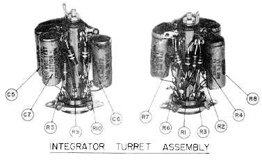
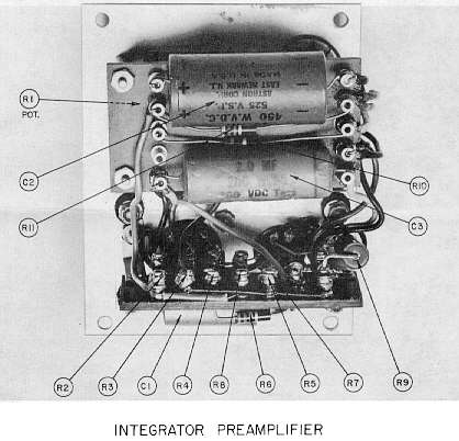
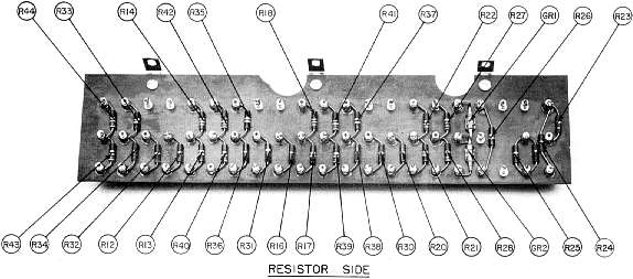
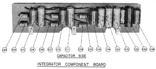
The schematic drawings attached for the Integrator Unit G21407 and the Power Supply B21442 indicate the normal voltages and the names of the component parts, as well as the voltages expected at various points in the circuit when measured with a 20,000 ohm per volt voltmeter.
FAIRCHILD RECORDING EQUIPMENT COMPANY
154th Street & 7th Avenue
Whitestone, 57, New York
Drawings:
G21407 - Integrator Unit
B21442 - Power Supply
B21476 - Amplifier
Click On The Thumbnails To Load Full Size Drawing.
Some are large and will take a minute or more to download.