The Colortek Optical Stereophonic Sound Film System
By JOHN MOSELY, KEITH O. JOHNSON,
and DAVID E. BLACKMER
Colortek is an optical sound system rendering four separate unilateral variable-area audio tracks and a central control track, all within the area of the present monophonic variable-area and variable-density soundtrack location as defined by American National Standard PH22.40-1967. The innovative design of the system employs, as a sound reader, a charge-coupled-device scanner (CCD scanner) and applies video technology to the read-out of soundtracks. It scans the four soundtracks transversally at 10 MHz, resulting in a CCD frame rate of 40 kHz, as the tracks pass longitudinally at the normal speed of 24 film frames/s (457.2 mm/s) through the sound reader. The electronic drive of a Westrex light valve has been modified to obtain the new soundtrack configuration. No ground-noise-reduction device or circuit has been incorporated, because the design of the CCD scanner suppresses ground noise almost completely. The soundtrack may also be reproduced on projectors with a normal optical sound head. However, due to the use of electronic companding and to the lack of ground-noise suppression, the reproducing electronics should be modified to reproduce the four-track format correctly. This format can be reproduced monophonically as well as stereophonically. Both the frequency and dynamic ranges of the recording light valve have been extended to achieve faithful transfer from the magnetic to the photographic printing medium and faithful reproduction in the theater. By the use of matrix encoding, the system can be extended to accommodate six separate channels of sound for surround sound effects in 35mm theatrical presentation. The narrow center control track serves several purposes: (1) it enables the CCD scanner to recognize and compensate automatically for any side weave of the soundtrack; (2) it serves as an image-spread monitor for correcting, within limits, distortions caused by image spread; (3) it can be used to trigger special sound effects or auditorium speaker groups as encoded on the control track; (4) it also can be used for automatized general theater operation. A specially designed compander completes the system.
Design Goals
The Colortek system has been designed to accomplish modern high-fidelity multi-channel optical recording. Data about multi-channel sound were published in a previous paper by this author.' The desired performance specifications are given in Table I.
Several fundamental requirements were considered essential to the overall design. (1) The theater equipment should be reasonably priced. (2) The equipment must be self-aligning over a wide range of electrical and mechanical deviations. (3) Failure areas must be easily identified and corrected by modular replacement. (4) The entire system should be easily and positively checked by means of go-no-go tests for effective maintenance. (5) The equipment must meet state-of-the-art specifications and must be susceptible to easy updating in the field.
For many and good reasons magnetic striped soundtracks never became a generally accepted medium for theater use. They are used sometimes for special showcase stereophonic versions of high-budget pictures. While the quality of optical recordings has not kept pace with the magnetic recording medium, cost and production complications make magnetic release recording impracticable. Thus it was decided to investigate more fully the possibility of producing a high-quality multi-channel optical soundtrack. Its only constraint was the requirement that it be mechanically playable not only on the sound reader specifically designed for it but also on existing optical sound readers.
Basic Components and Features
Four items characterize the stereophonic Colortek system: its light valve, its charge-coupled-device scanner (CCD scanner), its compander and its multiple purpose control track. Before giving a detailed description of each of these elements, let us briefly mention their basic aspects.
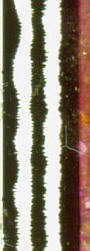
The light valve. After considering different types of modulators it was concluded that the most practical solution to producing four discrete tracks (which seemed to be the normal design requirement) lay in dividing the accepted dual bilateral variable-area track into four separate unilateral tracks. Westrex had made four-ribbon variable-density valves (Fig. 1), which after being turned 90° can also yield a variable-area recording. They had also made a three-ribbon light valve for Dr. Frayne's two-channel stereophonic system.2By rearranging the electrical connections to the four-ribbon valve and implementing the appropriate electronics, four unilateral and separate recordings can be obtained (Fig. 2).
The basic drawback to the use of unilateral tracks is their susceptibility to distortion produced by misalignment. Peak-to-peak weave of as much as ±0.01 in is sometimes present. Both weave and crosstalk are liable to produce distortion. Therefore, it was necessary to design a system able to overcome these limitations. The allowable overall modulation has been set at 16 X 103 in peak to peak, that is, ±0.008 in. All these conditions place stringent requirements upon the permissible noise level of the electronics, requirements, we believe, with which the Colortek system has successfully complied.
The CCD scanner.
This is the greatest innovation of the Colortek system. The CCD scanner consists of 256 cells arranged in a single line in a transversal position  with respect to the direction of travel of the film. This gives satisfactory resolution over the full track width. The CCD scans the soundtrack transversally at a rate of 40 kHz while the soundtrack advances at the normal speed of 18 in/s (457.2 mm/s). Film travel displacement per unit scan is thus 0.00045 in (0.01143 mm), The clocked video output of the CCD scanner is taken to a central processing unit containing the ancillary logic, power, switching and output circuitry. Here the video signal generated by the CCD scanner is converted into the desired audio signal. This audio signal, however, is derived only from the edge which separates the Dmax from the Dmin area of the soundtrack. In other words: the CCD scanner "sees" only the image edge and does not take into account the full width of the transparent or dark areas of the soundtrack or their variable ratio. The edge-derived signal has the enormous advantage that dirt, scratches or residual graininess throughout the greater part of the soundtrack area will simply not reproduce as ground noise. Noise will only become audible if its source is located on or immediately adjacent to the image boundary, for which
possibility the statistical probability is very low. The CCD scanner
recognizes the image edge by a process called "electronic slicing"
(explained later), which is tied in with a given intermediate density in the
boundary transition zone from the minimum to the maximum density of the track.
with respect to the direction of travel of the film. This gives satisfactory resolution over the full track width. The CCD scans the soundtrack transversally at a rate of 40 kHz while the soundtrack advances at the normal speed of 18 in/s (457.2 mm/s). Film travel displacement per unit scan is thus 0.00045 in (0.01143 mm), The clocked video output of the CCD scanner is taken to a central processing unit containing the ancillary logic, power, switching and output circuitry. Here the video signal generated by the CCD scanner is converted into the desired audio signal. This audio signal, however, is derived only from the edge which separates the Dmax from the Dmin area of the soundtrack. In other words: the CCD scanner "sees" only the image edge and does not take into account the full width of the transparent or dark areas of the soundtrack or their variable ratio. The edge-derived signal has the enormous advantage that dirt, scratches or residual graininess throughout the greater part of the soundtrack area will simply not reproduce as ground noise. Noise will only become audible if its source is located on or immediately adjacent to the image boundary, for which
possibility the statistical probability is very low. The CCD scanner
recognizes the image edge by a process called "electronic slicing"
(explained later), which is tied in with a given intermediate density in the
boundary transition zone from the minimum to the maximum density of the track.