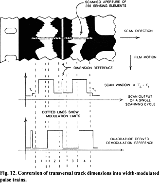
this operating point makes this distortion substantially lower than is normally found with a conventional average-area reader. Therefore a reference track of known dimension (the control track) is recorded together with the audio information. The circuit logic compares this reference pulse width to an internal record image scale factor. Small errors generate a differential correction voltage, offsetting the slicing point, for the lowest distortion. By this technique, high-quality reproduction is ensured for transmittance variations resulting from normal laboratory processing tolerances. Direct-current offset, or envelope rectification voltages, frequently generated by speech sibilance, are reduced together with their expansion during playback.
Normally, the slicing level is close to 50% of the minimum/maximum transmittance when the edge image projected on the CCD has an exponential or Gaussian distribution, starting from the minimum transmittance region. Under these conditions, the scaled CCD-derived pulse width will be proportional to the object image size, with first-order independence from minor focus errors. At this level, dirt having a lower transmittance and emulsion scratches having a greater transmittance, if falling reasonably outside of the 50% transition zone, will not reproduce as pulses and therefore as neither signal nor noise. Two sources of noise remain: (1) very large particles of high optical density, or severe emulsion scratches, will reproduce as noise, together with (2) anomalies occurring within the transition zone. There is a low probability for the occurrence of transition anomalies, where the noise duration is equal to the ratio of the particle size in the transition zone to the full-channel track width. Noises from these two sources reproduce with about the same intensity as on conventional uncompanded Academy tracks, played on a normal reader. However, it will be appreciated that the statistical probability for the occurrence of both types of noise occurring is very low.
The center slice point is set as a ratio of illumination intensities, rather than an absolute illuminance. Thus reasonable changes of the CCD illumination will alter the slicing transmittance from which the pulse train is derived. Normal lamp aging and the buildup of optical dirt will cause a slight noise increment, due to less than optimum operation of the CCD. However, the more important signal levels and crossmodulation settings will not drift.
Operation of the Scanner.
The Colortek system relies upon the usage of a commercial CCD operating near its maximum useful clock frequency. The availability of this device, at the present stale of the art makes the system practical. The 256-cell buried-channel CCD has a practical maximum clocking and cell-to-cell shift rate of about 10 MHz. This limit, which is imposed by using an optimum combination of drive currents, illumination intensity requirements and operating dynamic range, gives a 20-µs scan window. After adding the reset and scan start conditioning signals, the overall cycle time is 25-µs yielding a 40-kHz scan rate. The complete resulting waveform from the total scan of a dual bilateral track is shown in Fig. 14 The upper information frequency limit which is restricted by filtering and sampling methods, is normally at best 2.7 time less than the sample rate. This gives maximum useful frequency response of 1 kHz. The scanned CCD slit is 17 µm wide and 3.3 mm long, which also makes the scaled useful short-wavelength aperture limit correspond to 15 kHz, The cells are 13 µm wide, allowing a 75% modulate quarter track signal with the necessary guard band scaling to sweep 30 of them. An expected peak dynamic range of 46 dB gives an equivalent noise modulation of less than 1/3 cell, or 4 µm peak to peak.

