Fast rise pulses
are made by holding the minimum and maximum long-term averaged transmittance
levels and dividing these into an intermediate level applied to one input leg
of a voltage comparator. The raw filter output, fed to the other leg, gives
comparator output pulses, starting and ending at the slicing points of the
predetermined optical density. Additional compensation circuits are used to
prevent start conditioning, IR blooming and slicing errors caused by dispersion
effects from altering the averaged sliced level.
Noise From Scratches and Dirt.
Most dirt contamination and wear scratches will not
exceed the optimum slicepoint density at the clear film areas. As long as these
are away from the transition boundary, this noise is very small, mainly from
second-order scattering and reflections of the light beam. Deep scratches in
the Dmax area cutting through the emulsion and giving densities less than the
slicing point will reproduce as extra pulses, which could cause about the same
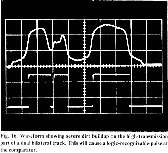
electrical noise as average-area readings (Fig. 16). These pulses will also
cause count errors on the overall scan window edge transition train, which by
necessity are electronically recognized in order to prevent channel mixup. If
such extraneous pulses occur, holding circuits stay active, thereby rejecting
scan frames with this problem and maintaining the demultiplexed levels of the
last good scan window. This technique is similar to dropout compensation in
video recorders, except that in this usage, extraneous unwanted signals are
removed and an almost inaudible hold or fill in occurs.
Dirt and scratch
anomalies occurring to any degree in the transition zone will reproduce with
intensities slightly higher than with a conventional reader. The probability of
this occurring is closely equal to the ratio of anomaly size and transition
zone width to channel track width. This noise has fewer
events per unit time and is, therefore, more impulsive than average
illumination reading. However, the overall rms level falls more than 10 dB
below the conventional reading of the same track geometry.
Readback of Four Discrete Channels.
The Colortek record format resembles the conventional
variable-area dual bilateral soundtrack, except that the four boundaries
modulate independently of each other. Ground-noise reduction is not used, in
order to maintain a fixed average center line of each modulated boundary and to
permit recording down to 20 Hz and below for special applications. These
modulated line boundaries, plus a dimension reference septum track, allow
several ways of decoding and correcting mechanical transport noise, jitter
and film weave.
One decoding method generates positive-going
pulses for each edge transition. The off-going edge is from a free-run
generated square wave 90° out of phase with respect to the average transition
boundaries. The polarities are set so that the average image train subtracted
from the reference square wave gives zero volts, when the 90° phase
relationship holds. Small phase errors translate into dc offset voltages, which
operate a variable-delay, gated, voltage-controlled oscillator. With correct
polarities, the closed-loop system will vary its time delay to lock onto the
signal PWM train. It also gives the position or time-reference transition
needed to demodulate each channel edge. Changing the frequency portion of the
reference oscillator corrects for magnification changes, which can occur in
recording or in focusing the reproducer objective. Both of these control
actions permit centering of the demodulation time reference, making the system
insensitive to film weave and allowing high modulation on each track.
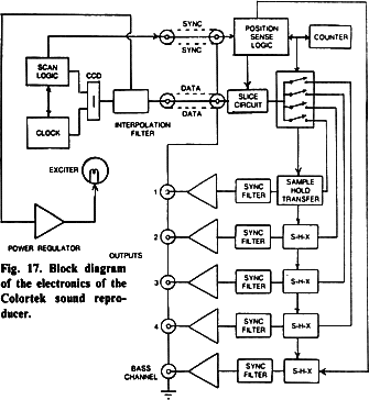
Individual channels are commutated
as transition edge to reference square wave edge variable-width
constant-current pulses. These pulses, when presented to individual channel
capacitors, yield an area-proportioned voltage which is held until all channels
and the reference track have been commuted and the edge transitions counted.
When this end-frame count is correct, all charges are transferred to receiving
low-pass synchronous filters, which remove the commutation components and
smooth the waveforms. Improper counts, resulting from dirt or gross errors such
as splices, will not develop a transfer signal, thus preventing the low-pass
filter from being clocked to accept new charges. Thus, gross noise and spurious
channel mix-up are largely eliminated.
A rough time-delay aperture
equalizer is built into the low-pass filter, to help reduce ringing and pre-shoot
occurring with sharp wavefronts. This degree of sophistication is necessary to
ensure accurate RMS detector tracking of the expander control circuitry. This
technique minimizes the audibility of small, rapid level changes which are
caused by voice articulation transients.
Cross-modulation Control.
Most optical low-order cross-modulation occurs from image spread or shrinkage.
This causes the average area of a symmetrically modulated signal to shift as a
function of modulation frequency and density. Commonly encountered
short-wavelength fill and peak rounding will cause equal distortion for
unilateral, bilateral and dual bilateral recordings. Push-pull dual bilateral
modulated tracks cancel this type of first order distortion, but some third
harmonic and level compression still remains.

