 The Compander
The compander noise-reduction systems for
motion-picture applications have special problems which require special solutions
that are unique to this application. Optical sound has a number of sources of
impulse noise. Imperfections in the film base or dirt in any step of exposure
of processing cause both light-transmitting and light-occluding areas which
often cause an impulsive error of as much as several tens of milliseconds'
duration.
Dirt and scratches on the film
surface cause progressive deterioration of the SNR as a given print is
projected a number of times. The grain structure of both the negative and
positive limits the SNR. The scanning and level slicing processes in the
Colortek system reduce both image structure noise and surface noise
significantly, but the resulting SNR is somewhat worse than that of a good
domestic cassette recorder.
One of the design requirements of
the Colortek system is flat, low-frequency response to 20 Hz. Ground-noise reduction is
impractical to use with this extended low-frequency response, as the
ground-noise response time would have to be over 50 ms to prevent excessive
low-frequency popping on attack. Such a long response time would require a
corresponding signal delay in the recording apparatus and would result in an
excessive anticipatory hiss and noise increase before each fast signal attack.
The noise spectrum of a typical
film system is shown in Fig. 3, along with data on cassette tape, master
magnetic tape and applicated magnetic stripe on film. These data were taken
with a 1% bandwidth analyzer which would render "pink" noise as a
straight horizontal line on the graph. For good psychoacoustic reasons,
recording systems have minimum noise annoyance with an equalization pattern
which yields approximately pink noise over the intended signal bandwidth.
A number of noise-reduction methods
were considered for the Colortek system. Multiband systems such as Dolby and Telcom
were ruled out on the basis of high cost per channel and their tendency to respond
rapidly to impulse noise added by the recording medium, thereby resulting in a
large gain overshoot in the presence of an impulse noise event. This property
may be deduced directly from the tone burst overshoot of the noise-reduction
encoder. Systems which have little or no transient overshoot in the encode mode
must, of necessity, be quite sensitive to impulse noise.
A single-band linear decibel
compander was selected as the optimum system on the basis of performance and
cost. A compression/expansion ratio of 2.3:1 was chosen to yield a
signal-to-background noise range of 90 dB from the approximately 43 dB SNR of
each track. Because the operation of this system is not necessarily obvious,
its relationship will be described.
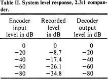
Linear decibel compression operates
in the manner shown in Table II. The compressor and expander are arranged for
convenience to have unity gain at signal reference level. With an input of —80
dB, recording level is -34.8 dB, which is well above the noise floor of the
recording process.
The -43 dB noise of the soundtrack itself results in an output
noise of about —99 dB which is clearly imperceptible in any theater
environment.
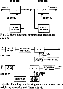
The circuit
configuration used to achieve linear decibel compression is shown in Fig. 20. A
voltage-controlled amplifier with logarithmic control response is driven from a
level sensor which has an output proportional to the logarithm of the signal
level. With an appropriate gain in the control path, a 2.3:1 compression and
expansion ratio is established over a wide dynamic range. Note that the decoder
will track the encoder accurately at any level because the expansion ratio is
invariant.
The level-sensor
time response is of great importance in achieving an optimum noise-reduction
system for optical sound. If peak-level sensing is used, transient overshoot
in the encoder may be completely eliminated, but impulse noise reaching the
decoder will cause large errors in gain. On the other hand, a slow-level sensor
results in large overshoots in the encoder and very low sensitivity to impulse
noise in the decoder. The optimum system in terms of psychoacoustic damage to
the program material lies between these two extremes. Because the encoder and
decoder level detectors must of necessity be essentially similar, a compromise
time response with about 10 ms settling time for a step function input has
been found to be optimum. Most actual music and speech transient attacks have
over 10 ms rise time and those few which are faster do not suffer much audible
degradation due to the soft clipper in the light valve drive circuit. The
response to impulse noise inputs to the decoder is, however, much less than
with a peak detector. Tone burst attack data for several common
noise-reduction systems have been described in an engineering bulletin from
Gotham Audio.3
It is necessary
to add spectral control filters and weighting networks to this system to
optimize the noise spectrum and to eliminate the effects of noise outside of
the audio bands. The complete circuit is shown in Fig. 21. The weighting curve
used in the record circuit signal path is shown in Fig. 22. A similar curve is
used in the level sensor path with the result that the encoder sine wave sweep
response is nearly flat, with some high-frequency ducking to minimize
high-frequency crossmodulation products.